
Introduction
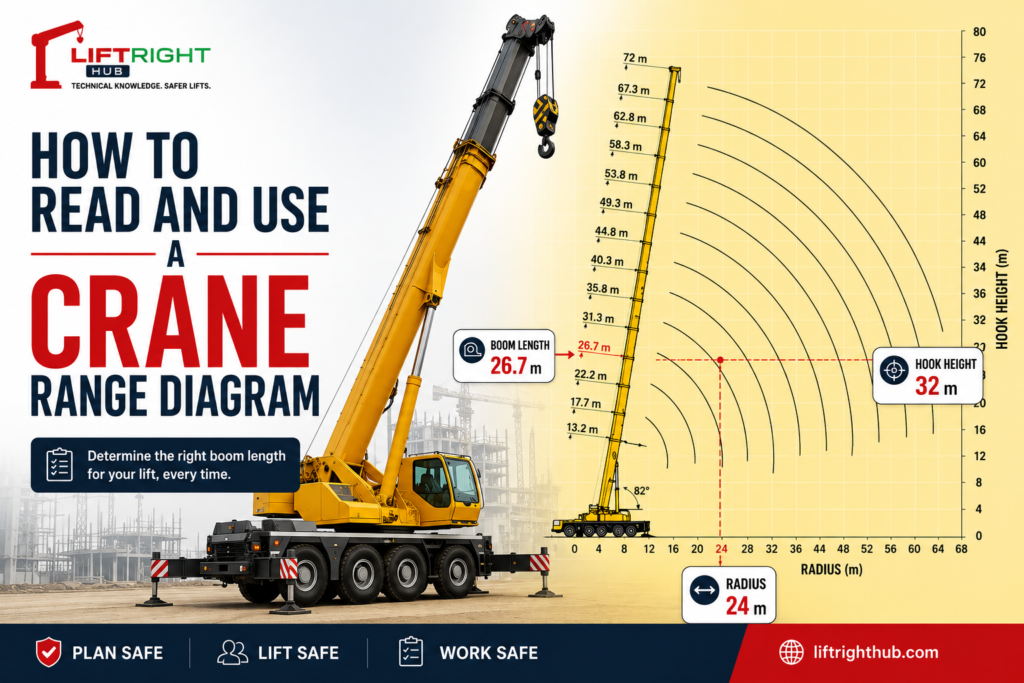
A crane range diagram is one of the most important tools used during lift planning. It helps determine the boom length required to reach a specific lifting radius and hook height before consulting the crane load chart.
Understanding how to read and use a range diagram correctly is essential for Appointed Persons, Lifting Supervisors, Lift Engineers, and Crane Operators.
In this article, we will explain the purpose of a crane range diagram and demonstrate a practical method for determining the required boom length for a lifting operation.
What Is the Purpose of a Crane Range Diagram?
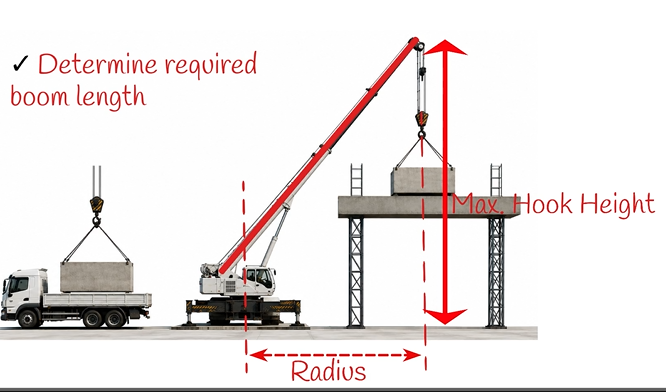
The primary purpose of a crane range diagram is to determine the boom length required for a lift.
If you know:
- The working radius
- The required lifting height
You can use the range diagram to determine the minimum boom length necessary to safely perform the lift.
The working radius is measured from the centre of crane rotation to the centre of the hook block.
The lifting height is measured from ground level to the boom tip.
Once the required boom length has been established, the crane load chart can then be consulted to verify whether the crane has sufficient lifting capacity at the selected radius and boom length.
Understanding the Crane Range Diagram
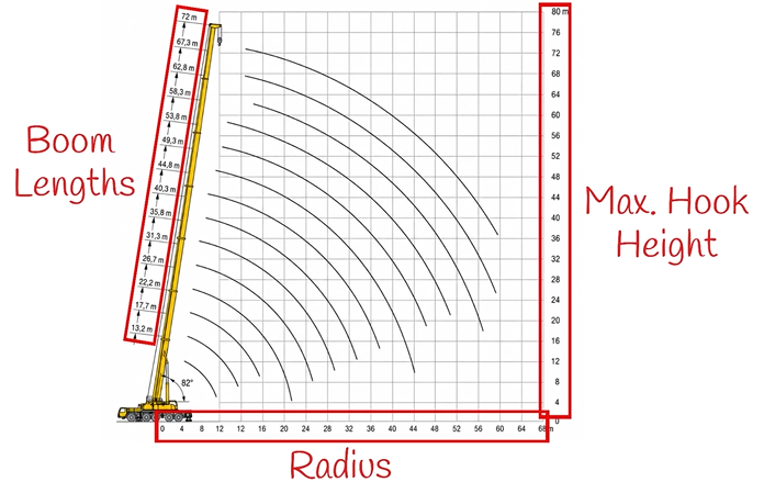
A typical crane range diagram consists of:
Horizontal Axis
The horizontal axis represents the crane radius.
Vertical Axis
The vertical axis represents the maximum hook height.
Boom Length Curves
The curved lines on the diagram represent different boom lengths.
Each curve corresponds to a specific boom configuration available on the crane.
The point where the required radius and hook height intersect determines the boom length required for the lift.
Practical Example
Let us consider the following lifting scenario.
Step 1 – Determine the Working Radius
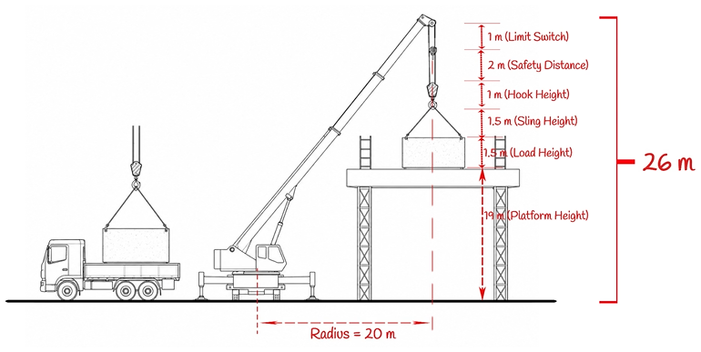
Assume the distance from the centre of crane rotation to the centre of the hook block is:
20 metres
Therefore:
Working Radius = 20 metres
Step 2 – Determine the Required Vertical Height
The lift requires:
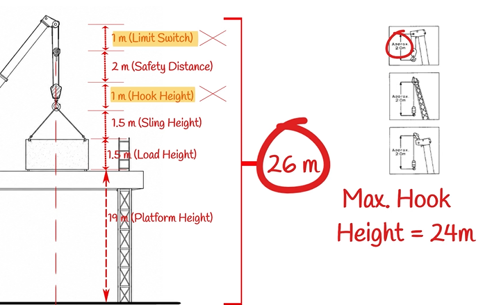
| Component | Height |
| Platform Height | 19 m |
| Load Height | 1.5 m |
| Sling Height | 1.5 m |
| Hook Height | 1 m |
| Safety Clearance | 2 m |
| Anti-Two-Block Clearance | 1 m |
Total Height:
19 + 1.5 + 1.5 + 1 + 2 + 1
Total Vertical Height = 26 metres
Step 3 – Determine the Required Hook Height
Range diagrams may be presented differently depending on the crane manufacturer.
Some diagrams measure from the boom tip.
Others measure from the maximum hook height.
For this example, we will use a range diagram based on maximum hook height.
Therefore:
Required Hook Height = Total Height − Hook Height − Anti-Two-Block Clearance
Required Hook Height = 26 − 1 − 1
Required Hook Height = 24 metres
Step 4 – Locate the Radius and Hook Height
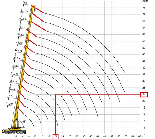
Locate:
- Radius = 20 metres
- Hook Height = 24 metres
The point where these two values intersect represents the lifting requirement.
Step 5 – Select the Required Boom Length
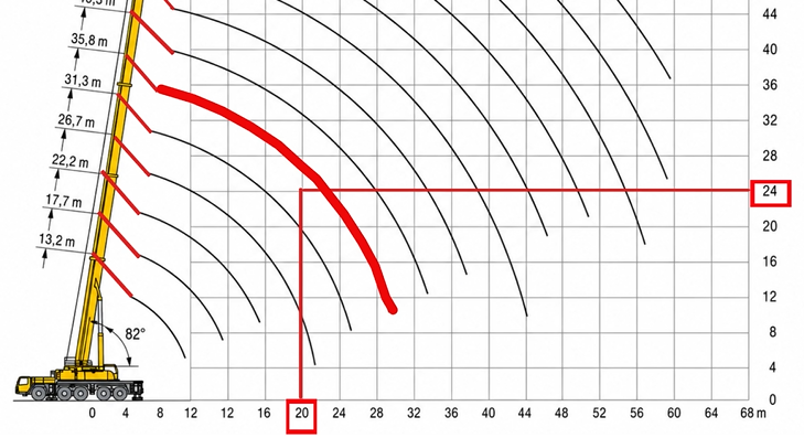
The intersection point falls between:
- 31.3 metre boom length
- 35.8 metre boom length
Since the crane cannot be configured with a boom length shorter than required, the next available boom length must be selected.
Therefore:
Required Boom Length = 35.8 metres
Important Reminder
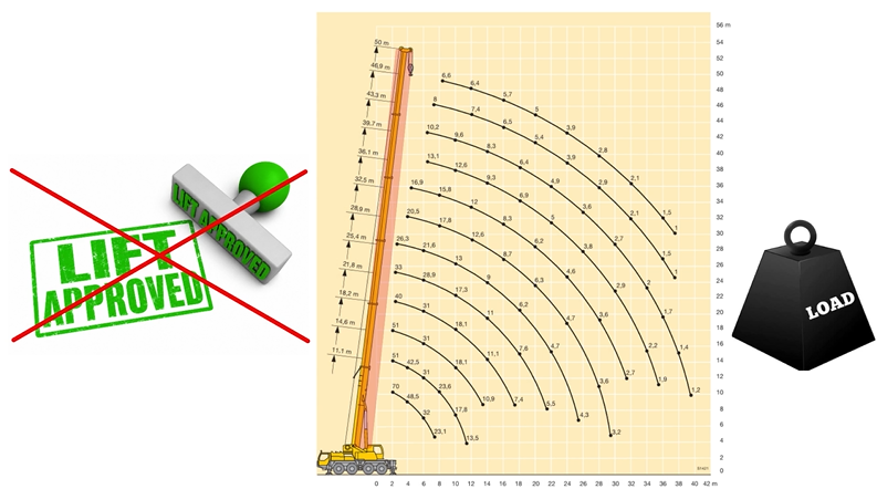
A crane range diagram only determines the boom length required to reach the load.
It does not verify whether the crane can safely lift the load.
After determining the required boom length, always consult the crane load chart to verify:
- Available crane capacity
- Radius limitations
- Boom configuration
- Counterweight configuration
- Outrigger configuration
Never approve a lifting operation using the range diagram alone.
Common Mistakes When Using a Range Diagram
- Using the load height instead of hook height.
- Forgetting to include sling height.
- Ignoring hook block dimensions.
- Ignoring anti-two-block clearance.
- Selecting the shorter boom length.
- Failing to verify the load chart after selecting the boom length.
Conclusion
A crane range diagram is an essential lift planning tool used to determine the boom length required for a lifting operation.
By identifying the required radius and hook height, lift planners can select the correct boom length before consulting the crane load chart.
Remember that the range diagram only determines reach. The crane load chart must always be checked to confirm lifting capacity before the lift is approved.
Next Lesson: How to Select the Correct Crane Capacity from the Crane Load Chart